|
A recent chat on All Programmable Planet about the most unusual FPGA-based applications anyone has run across, or been involved with, resulted in some interesting discussions. These conversations were not focused only on the tasks for which FPGAs have been employed (switched-mode power supply controllers replacing analog components, for example), but also some applications for which a lot of people new to FPGA development appear to have an interest. One recurring topic was the use of FPGA in image processing. Thanks to their nature, FPGAs are well suited to the intense levels of signal processing required by many imaging systems. Of course, one of the most rewarding aspects of image processing is seeing the resultant image on a display, and a very common form of display uses the VGA (video graphics array) standard. The first VGA display was introduced with the IBM PS/2 line of computers in 1987. One thing most people associate with this form of display is the 15-pin D-subminiature VGA connector you tend to find on the back of a tower computer or the side of your notebook computer.
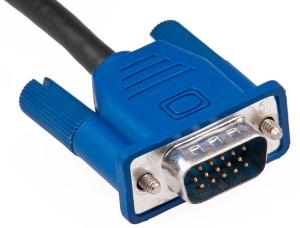 A 15-pin D-subminiature VGA connector. A 15-pin D-subminiature VGA connector.
The original VGA standard supported a resolution of only 640x480 (which means 640 pixels in the horizontal plane and 480 lines in the vertical plane). Over the years, however, the standard has evolved to support a wide variety of resolutions, all the way up to widescreen resolutions as high as 1920x1080. The act of driving a VGA is surprisingly simple, being based on the use of two counters as follows:
- Pixel counter: Counts at the required clock frequency (40MHz in this example) the number of pixels in a line, this is used to generate the horizontal timing.
- Line counter: Also known as the Frame Counter, this repeats at the refresh rate of the desired VESA specification for 60Hz, 75Hz, 85Hz, and so on. This also identifies when the counter is within a valid region for outputting display data. The line counter is incremented each time the pixel counter reaches its terminal count.
These counters are used to generate two synchronization (sync) markers -- the "V_Sync" (vertical sync) and "H_Sync" (horizontal sync) signals. In conjunction with the RGB (red, green, and blue) analog signals , "V_Sync" and "H_Sync" form the basic signals required to display video on a monitor. Actually, this may be a good time to take a step back to remind ourselves as to the origin of terms like "V_Sync" and "H_Sync." The main thing to remember is that, at the time the original VGA standard was introduced, the predominant form of computer display was based on the cathode ray tube (CRT), in which an electron beam is used to "write" on a phosphorescent screen.
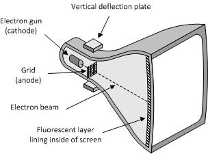 Cross-section of cathode ray tube (CRT). Cross-section of cathode ray tube (CRT).
There are several ways in which an electron beam can be manipulated to create images on a CRT screen, but by far the most common technique is the raster scan. Using this approach, the electron beam commences in the upper-left corner of the screen and is guided across the screen to the right. The path the beam follows as it crosses the screen is referred to as a line. When the beam reaches the right-hand side of the screen it undergoes a process known ashorizontal flyback, in which its intensity is reduced and it is caused to "fly back" across the screen. While the beam is flying back it is also pulled a little way down the screen as shown in the following illustration:
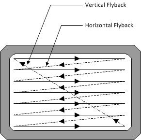 Path of the electron beam when using the raster scan technique. Path of the electron beam when using the raster scan technique.
The beam is now used to form a second line, then a third, and so on until it reaches the bottom of the screen. The number of lines affects the resolution of the resulting picture (that is, the amount of detail that can be displayed). When the beam reaches the bottom right-hand corner of the screen it undergoes vertical flyback, in which its intensity is reduced, it "flies back" up the screen to return to its original position in the upper left-hand corner, and the whole process starts again. The "V_Sync" and "H_Sync" signals are used to synchronize all of these activities. Thus, returning to our pixel and line counters, the values on these counters can be decoded so as to generate the required waveforms on the "V_Sync" and "H_Sync" outputs from an FPGA (that is, on the FPGA's pins that are being used to drive the display's "V_Sync" and "H_Sync" signals). Meanwhile, generating the RGB signals will require the FPGA to drive three digital-to-analog convertors (DACs), one for each signal. As the design engineer, you must ensure that the latency through the DACs is accounted for to ensure that their outputs are correctly aligned with respect to the "V_Sync" and "H_Sync" signals. The line and pixel counters both have portions of their count sequences when no data is being output to the display. In the case of an 800x600 resolution display refreshing at 60Hz, for example, the vertical (line) counter will actually count 628 lines while the horizontal (pixel) counter will count 1,056 pixels. Why should this be so? Well, returning to our raster scan, it takes a certain amount of time for the electron beam to undergo its horizontal and vertical flyback activities. One way to think about these times is that we have an actual display area that we see, and that this actual display area "lives" in a larger (virtual) display space that contains a border zone that we don't see:
 Actual display area surrounded by virtual display zone. Actual display area surrounded by virtual display zone.
Of course, in the case of today's flat-screen, liquid crystal displays (LCDs) and similar technologies, we don't actually need to worry about things like horizontal and vertical flyback times. At least, we wouldn’t have to worry if it were not for the fact that we don't actually know what type of screen our FPGA is driving. Thus, anything driving a VGA output generates the timing signals required to drive CRT display, and other forms of display simply make allowances for any of the historical peculiarities associated with these VGA signals. But we digress… Each of our counters has a collection of associated timing parameters. Vertical timings are referenced in terms of lines, while horizontal timings are referenced in terms of pixels. The following values are those associated with a display resolution of 800x600:
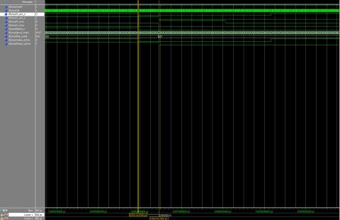
Using this approach, it is very easy to generate a simple VGA interface and see the results of our image processing algorithms on a monitor. Below you can see some of the simulation results I obtained from my VHDL representations of these counters:
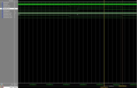 Simulation results for horizontal backporch. Simulation results for horizontal backporch.
 Simulation results for horizontal frontporch. Simulation results for horizontal frontporch.
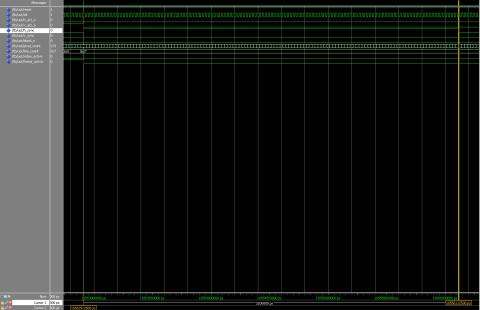 Simulation results for horizontal sync. Simulation results for horizontal sync.
| 
 [复制链接]


 发表于 2013-1-20 16:47:50


 发表于 2013-1-20 20:35:49

 /3
/3 

