

 717
717
1/ 背景简述 /
(1) 根据 SLVA477B Basic Calculation of a Buck Converter's Power Stage / 5 Output Voltage Setting小节中的如下描述:
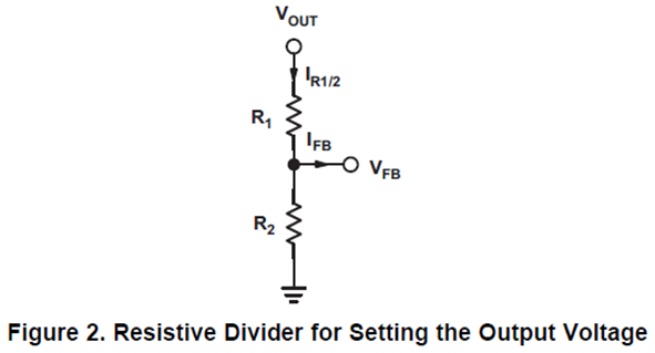
Almost all converters set the output voltage with a resistive divider network (which is integrated if they are fixed output voltage converters). With the given feedback voltage, VFB, and feedback bias current, IFB, the voltage divider can be calculated. The current through the resistive divider needs to be at least 100 times as big as the feedback bias current:
几乎所有转换器都使用电阻分压器网络设置输出电压(如果是固定输出电压转换器,则集成该网络)。使用给定的反馈电压VFB和反馈偏置电流IFB,可以计算分压器。通过电阻分压器的电流需要至少是反馈偏置电流的100倍:

This adds less than 1% inaccuracy to the voltage measurement and for the calculation of the feedback divider, the current into the feedback pin can be neglected. The current also can be a lot higher. The only disadvantage of smaller resistor values is a higher power loss in the resistive divider, but the accuracy is increased a little. With the preceding assumption, the resistors are calculated as follows:
这给电压测量增加了不到 1% 的误差,对于反馈分压器的计算,进入反馈引脚的电流可以忽略不计(也就是在I(R1R2) ≥ 100 * I(FB)的情况下,I(FB) 相对 I(R1R2) 是可以忽略的)。电流也可以高得多。电阻值较小的唯一缺点是电阻分压器中的功率损耗较高,但精度略有提高。根据上述假设,电阻的计算公式如下:
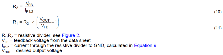
总结来说,基于上述公式(9)的方法,需要先使用公式(10)计算取值低边反馈电阻R2,再通过公式(11)计算取值高边反馈电阻R1。
(2) 根据 MPS电源小课堂第三季第十话:DC-DC变换器FB分压电阻设计( https://mp.weixin.qq.com/s/QB3rN7M4ydPl6JWyROGHaw ),总结到“因此,对于不同输出电压场景(1V / 1.2V / 1.8V / 2.5V / 3.3V / 5V),建议固定上分压电阻R1阻值,更改下分压电阻R2阻值,来获得近似的环路特性”。
所以,问题是:
① 在BUCK电路高边反馈电阻R1和低边反馈电阻R2的阻值中,是先确定R1,再计算R2?还是反过来?
② TI方法和MPS方法的本质区别在哪里?