

 2224
2224
前言:
在工业物联网和边缘计算场景中,多网口需求日益普遍。传统方案依赖进口交换芯片,不仅成本高昂,供应链风险也不容忽视。景略半导体(JLSemi)推出的JL6110国产交换机芯片,以其低功耗、高集成度的特性,成为国产化替代的理想选择。
本文基于眺望电子RK3568核心板平台,详细记录JL6110交换机芯片的MAC-to-MAC适配全过程,涵盖设备树配置、驱动移植、调试技巧及性能验证,为同类项目提供实战参考。
一、MAC-to-MAC连接架构
1.1 硬件连接方式
SoC内部MAC控制器与交换机芯片MAC采用RGMII直连方案:
MAC0 --RGMII-- MAC1
TXD[3:0] → RXD[3:0]
TX_EN → RX_DV
TX_CLK → RX_CLK
RXD[3:0] ← TXD[3:0]
RX_DV ← TX_EN
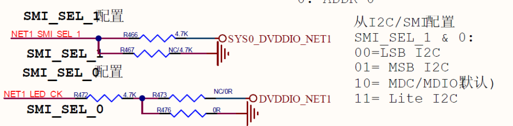
RX_CLK ← TX_CLK1.2 关键Strap Pin配置
JL6110的SMI_SEL引脚为典型Strap Pin(启动配置脚),用于选择管理接口类型:
| SMI_SEL_1 | SMI_SEL_0 | 模式 |
| 0 | 0 | I2C(LSB地址模式) |
| 0 | 1 | I2C(MSB地址模式) |
| 1 | 0 | MDIO / SMI(推荐) |
| 1 | 1 | Lite I2C |
推荐配置为10(MDC/MDIO模式),与RK3568 GMAC控制器兼容。
二、设备树配置详解
RK3568支持双GMAC控制器,均可配置为MAC-to-MAC模式:
&gmac0 {
    status = "okay";
    phy-mode = "rgmii";
    clock_in_out = "output";
    assigned-clocks = <&cru SCLK_GMAC0_RX_TX>, <&cru SCLK_GMAC0>;
    assigned-clock-parents = <&cru SCLK_GMAC0_RGMII_SPEED>;
    assigned-clock-rates = <0>, <125000000>;
    snps,reset-gpio = <&gpio0 RK_PD5 GPIO_ACTIVE_LOW>;
    snps,reset-active-low;
    snps,reset-delays-us = <0 10000 2000000>;
    pinctrl-names = "default";
    pinctrl-0 = <&gmac0_miim
             &gmac0_tx_bus2
             &gmac0_rx_bus2
             &gmac0_rgmii_clk
             &gmac0_rgmii_bus>;
    tx_delay = <0x4a>;
    // rx_delay = <0>;
    fixed-link {
        speed = <1000>;
        full-duplex;
    };
};
&gmac1 {
    status = "okay";
    phy-mode = "rgmii";
    clock_in_out = "output";
    assigned-clocks = <&cru SCLK_GMAC1_RX_TX>, <&cru SCLK_GMAC1>;
    assigned-clock-parents = <&cru SCLK_GMAC1_RGMII_SPEED>;
    assigned-clock-rates = <0>, <125000000>;
    snps,reset-gpio = <&gpio1 RK_PB0 GPIO_ACTIVE_LOW>;
    snps,reset-active-low;
    snps,reset-delays-us = <0 10000 2000000>;
    pinctrl-names = "default";
    pinctrl-0 = <&gmac1m1_miim
             &gmac1m1_tx_bus2
             &gmac1m1_rx_bus2
             &gmac1m1_rgmii_clk
             &gmac1m1_rgmii_bus>;
    tx_delay = <0x4a>;
    // rx_delay = <0x20>;
    fixed-link {
        speed = <1000>;
        full-duplex;
    };
};
&mdio0 {
rgmii_phy0: phy@0 {
compatible = "ethernet-phy-ieee802.3-c22";
reg = <0x0>;
};
};
&mdio1 {
rgmii_phy1: phy@0 {
compatible = "ethernet-phy-ieee802.3-c22";
reg = <0x0>;
};
};
⚠️ 关键配置说明:
- fixed-link节点表示MAC-to-MAC直连,无需外部PHY
- phy-handle属性需注释掉,避免驱动尝试外部PHY通信
- tx_delay值需根据实际PCB走线调整(通常0x4a-0x50)
三、JL6110驱动移植
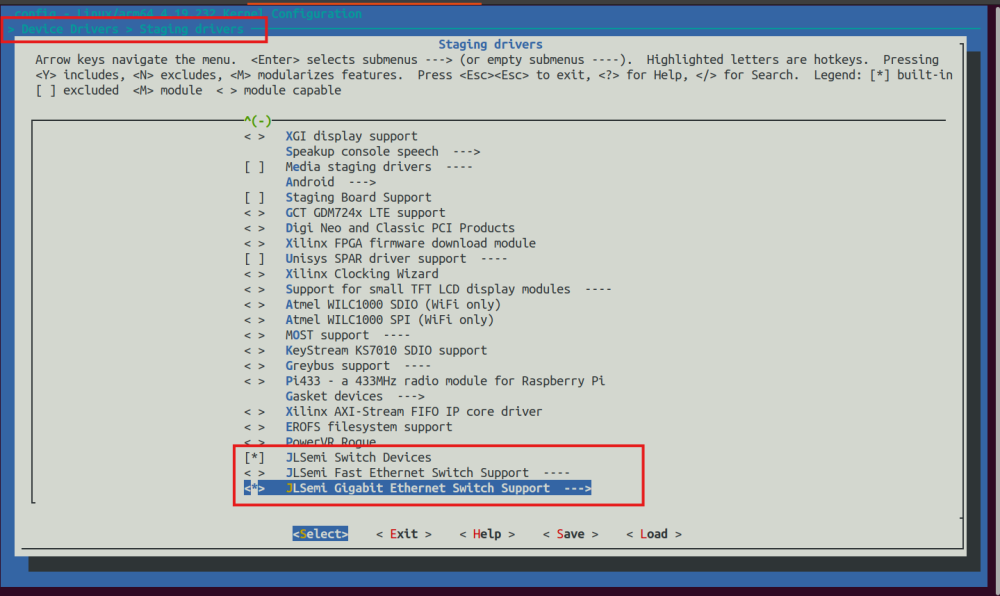
3.1 内核配置
移植JL6110 SDK后,需在内核配置中启用SMI interface支持:
Device Drivers → Network device support → Ethernet driver support →JLSemi Switch Support → SMI interface
3.2 驱动适配
JL6110驱动使用port_mdio_read/port_mdio_write函数与硬件通信,需适配为RK3568内核的mdiobus_read/mdiobus_write接口:
extern struct mii_bus *jl_mii_bus, *jl_mii_bus1;
void port_mdio_write(jl_io_desc_t *io_desc,
            jl_uint8 phy, jl_uint8 reg, jl_uint16 val)
{
    if ((io_desc->smi.mdio.bus_id & 0xffffff)==0) {
        mdiobus_write(jl_mii_bus, (int)phy, (u32)reg, val);
    } else if ((io_desc->smi.mdio.bus_id & 0xffffff)==1){
        mdiobus_write(jl_mii_bus1, (int)phy, (u32)reg, val);
    }
}
jl_uint16 port_mdio_read(jl_io_desc_t *io_desc,
            jl_uint8 phy, jl_uint8 reg)
{
    int data = 0;
    if ((io_desc->smi.mdio.bus_id & 0xffffff)==0) {
        data = mdiobus_read(jl_mii_bus, (int)phy, (u32)reg);
    } else if ((io_desc->smi.mdio.bus_id & 0xffffff)==1){
        data = mdiobus_read(jl_mii_bus1, (int)phy, (u32)reg);
    }
    return (jl_uint16)(data & 0xffff);
}
四、调试与验证
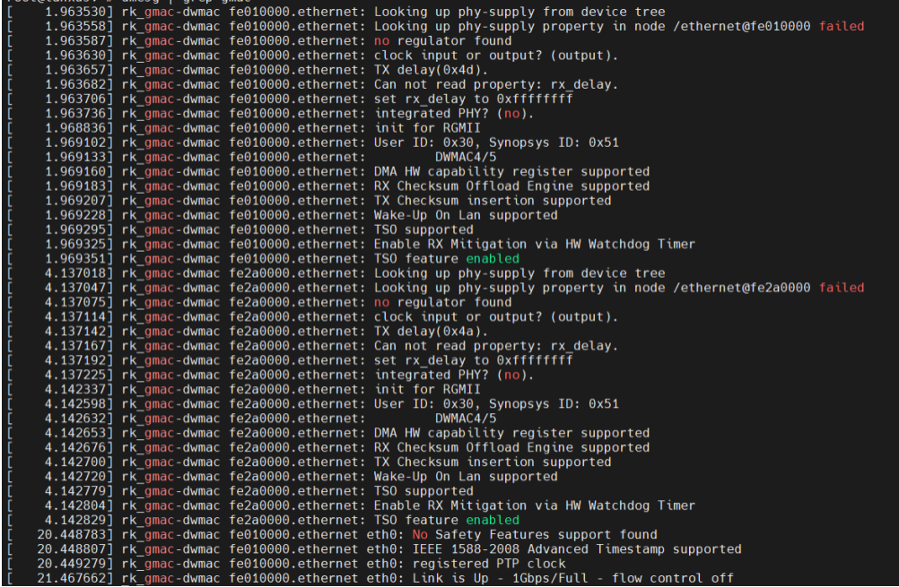
4.1 驱动加载检查
正常加载后,内核日志应显示:
网口驱动正常如下打印信息:

4.2 PHY ID验证
通过debug接口读取芯片ID确认通信正常:
echo -r -a 0x244008 -s 1 > /proc/jlmdio/debug  # 应返回0x937C
echo -r -a 0x24400C -s 1 > /proc/jlmdio/debug  # 应返回0x4031
4.3 功能实测
4.3.1 动态IP获取
将网线插入6个RJ45的任意一个,可执行以下命令手动获取 IP 地址:
ifconfig eth0 up
udhcpc -i eth0
ping www.baidu.com -I eth0 -c 5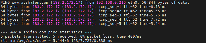
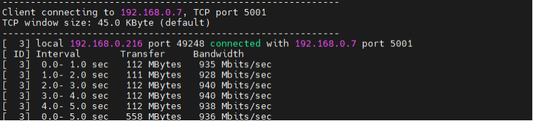
4.3.2 iperf带宽测试
iperf -c 192.168.0.7 -t 5 -i 1
带宽稳定在900Mbps以上。
4.3.3 光口测试&交换机功能测试
将光模块和光纤插上SFP1(系统节点为eth1),测试方法与电口测试方法一致。交换机其余网口之间可互通。
总结
通过本文介绍的MAC-to-MAC适配方案,眺望电子RK3568核心板可稳定驱动JL6110国产交换机芯片,实现:
✅ 双GMAC控制器同时工作
✅ 12路千兆电口+1路光口扩展
✅ 驱动层完整适配,内核级稳定运行
✅ iperf实测带宽900Mbps+
国产化替代不仅是供应链安全的选择,更是技术自主可控的必经之路。眺望电子将持续深耕国产化生态适配,为工业嵌入式领域提供可靠、可控的硬件解决方案。更多资料获取可以关注我们公众号或者同事联系获取。